
How to Calibrate a Dial Gauge (Step-by-Step Guide for Workshops)
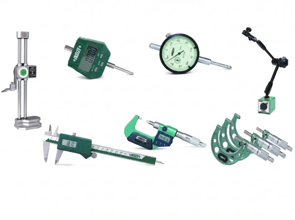
A dial gauge that reads perfectly fine on a quick check can still be quietly out of tolerance — and the only way to know for certain is to calibrate it against a traceable reference, not just eyeball the needle.
This guide walks through what calibration actually means for a dial gauge, the equipment you need, and the step-by-step procedure used in recognised standards such as ASME B89.1.10 and JIS B7503, so you can build a reliable calibration routine for your own workshop.
Need a dial gauge, comparator stand, or gauge blocks for calibration? Tell our team what you’re setting up and we’ll help you find the right equipment.
What Is a Dial Gauge?
A dial gauge — more formally an indicator, or dial indicator — is an instrument used to accurately measure small distances and angles and amplify them so they’re easy to read. The classic mechanical version provides a dial display similar to a clock face, where a hand points to graduations representing the distance the probe tip has moved from a zero setting.
Inside, a mechanical dial indicator works much like precision clockwork: a rack cut into the side of the probe shaft drives a pinion gear as the probe moves, spinning the indicator’s hand. Springs preload the gear mechanism to minimise backlash error in the reading.
Dial indicators typically measure ranges from 0.25 mm to 300 mm, with graduations from 0.001 mm to 0.01 mm on metric models. Dial size is commonly specified by American Gauge Design (AGD) number, from AGD 0 (25-35 mm diameter) up to AGD 4 (76-95 mm diameter).
A dial test indicator (also called a lever arm or finger indicator) is a related but distinct tool: instead of a probe that retracts linearly, its tip swings in an arc around a hinge point, which lets it measure inside narrow grooves and small bores a standard plunger-type probe can’t reach. Because it measures angular displacement rather than pure linear displacement, a dial test indicator is subject to cosine error whenever its stylus isn’t parallel to the surface being measured — a factor its own calibration standard, JIS B7533, accounts for separately.
Dial gauges are used to check tolerance variation during part inspection, to set up or calibrate a machine before a production run, and — one of the most common shop-floor uses — to indicate run-out when centring a workpiece in a lathe’s four-jaw chuck.
What “Calibration” Actually Means
The international vocabulary of metrology (VIM3) defines calibration as an operation that, under specified conditions, first establishes a relationship between the values given by measurement standards (with their own known uncertainty) and the corresponding readings from the instrument, and then uses that relationship to obtain a measurement result from a future reading.
In plain terms: calibration is a structured search for errors in a measuring instrument, checked against a reference of known, traceable accuracy — not a subjective “does this look about right” check.
What You Need Before You Start
- A reference standard — either a dedicated dial indicator calibrator, or a micrometer head or other length-measuring unit with a graduation of 0.5 μm or less and an instrumental error within ±1 μm, depending on the indicator’s own graduation.
- A supporting stand to hold the dial gauge securely and squarely during the check.
- Gauge blocks if you’re using the gauge block method rather than a dedicated calibrator, along with a flat measuring stage.
- A spring scale or force gauge (graduation 2 gf or less, or sensitivity 0.02 N or less) if you’re also checking measuring force.
- A stable 20°C environment — the tolerance tables used in dial indicator calibration standards apply at 20°C specifically.
Setting up a calibration station? Send us your requirements and we’ll help you find the right Mitutoyo or Insize equipment.
Step-by-Step: How to Calibrate a Dial Gauge
This procedure follows the approach used in ASME B89.1.10 (dial indicators) and JIS B7503, both of which check a small, defined set of measurands: repeatability, error of indication in both directions, and hysteresis.
- Secure the dial gauge on the calibrator or stand. Mount it with its spindle set vertically downward (the standard orientation for calibration), ensuring the spindle is in line with the intended measurement direction to avoid cosine-effect error.
- Take four readings across the first revolution. Displace the spindle upward, plotting the error at every 1/10 revolution of the pointer for the first two revolutions from the zero point.
- Continue over the full measuring range. Take readings at every half revolution for the next several revolutions, then at every full revolution after that — typically 6 to 10 readings in total over the indicator’s full range, depending on its size.
- Reverse the spindle at the end of the range and retrace the same points. Plot the error at the same positions measured during the upward (outward) displacement. The gap between the forward and retrace readings at the end point is the retrace error.
- Calculate hysteresis. Hysteresis is the difference between the error recorded during inward (clockwise) spindle movement and the error recorded during outward (counter-clockwise) movement at the same point. It’s a common failure mode in used or worn indicators, since it stems from minute changes in clearance between the internal gears.
- Check repeatability. Apply the contact point perpendicular to a measuring stage, displace the spindle quickly and slowly five times at one position, and record the maximum difference between the five readings.
- Check measuring force (if required). With the spindle held vertically downward, take spring-scale or force-gauge readings at the zero, middle, and end points of the range, in both directions. The maximum forward measuring force should not exceed 0.5 N, and the difference between maximum and minimum measuring force in one direction should not exceed 0.2 N.
- Compare every result against the tolerance table for the indicator’s specific graduation and measuring range (see below) to determine pass or fail.
If you’re using the gauge block method instead of a dedicated dial indicator calibrator, be aware of its main limitation: it does not normally check hysteresis, which is the most common failure mode on a used indicator. A single-point hysteresis check can be done by raising a gauge block into the indicator at a fixed point, then raising and lowering the spindle to measure that same point twice — any difference between the two readings is hysteresis — but this only tests one point in the range, not the full sweep a dedicated calibrator provides.
Reading the Results: Maximum Permissible Error
JIS B7503 sets maximum permissible errors for dial indicators by graduation and measuring range. As an example, for a common 0.01 mm graduation indicator with a 10 mm (or less) measuring range, evaluated at 20°C:
| Check | Maximum Permissible Value |
|---|---|
| Retrace error | 5 μm |
| Repeatability | 5 μm |
| Indication error — 1/10 revolution (adjacent accuracy) | 8 μm |
| Indication error — 1/2 revolution | ±9 μm |
| Indication error — one revolution | ±10 μm |
| Indication error — two revolutions | ±15 μm |
| Indication error — entire measuring range | ±15 μm |
Finer graduations (0.001 mm and 0.002 mm) carry proportionally tighter tolerances in the same standard. These permissible errors should be evaluated inclusive of the calibration’s own measurement uncertainty, not compared against the raw reading alone.
Digital Indicators: What Changes
For digital (Digimatic-type) indicators, a hysteresis check is normally not required and is often skipped, since the electronic measurement principle doesn’t carry the same gear-clearance failure mode a mechanical dial mechanism does. That said, it’s worth evaluating your own instrument type and application before deciding to skip it.
One practical note for digital indicators specifically: repeatability within 0.2 mm of the end of the stroke isn’t guaranteed. When setting the zero point or presetting a value, lift the spindle at least 0.2 mm from the end of the stroke first.
Common Mistakes in Dial Gauge Calibration
Documenting “What,” Not “Why”
A calibration record that only logs pass/fail values, without capturing why a given method or test point was chosen, makes it hard to know whether the procedure is still correct when tolerances or technology change later.
Relying on Gauge Blocks Alone and Missing Hysteresis
Since the gauge block method doesn’t normally check hysteresis, an indicator with worn gears can pass a gauge-block-only check and still fail in service. Whether this matters depends on how the indicator is actually used — but it’s a decision to make deliberately, not by default.
Testing Too Few Points
Four readings on the first revolution plus 6 to 10 readings across the full range is the standard depth of testing — a quick check at just one or two points won’t reliably catch retrace error or hysteresis that shows up elsewhere in the range.
Ignoring Temperature
The tolerance values in JIS B7503 apply specifically at 20°C. Calibrating in a shop that’s noticeably hotter or colder than that introduces an error source the tolerance table doesn’t account for.
Misaligning the Spindle
Mounting a dial indicator so its spindle isn’t in line with the intended measurement direction introduces cosine-effect error — a subtle but real error that has nothing to do with the indicator’s own internal accuracy.
Sourcing Dial Gauges and Calibration Equipment in Dubai
Khokhawala Trading LLC supplies precision measuring instruments in Dubai and across the UAE, including dial gauges, indicators, gauge blocks, and other inspection tools for manufacturing, engineering, and quality control.
KTRDG’s precision measuring instruments range includes products from Mitutoyo and Insize — two of the best-known brands in dimensional metrology, with Mitutoyo’s own standards being among those referenced in this guide.


With more than 35 years of industrial tool supply experience, Khokhawala Trading LLC serves manufacturers, CNC shops, fabrication companies, and engineering industries in the UAE.
Ready to shop precision measuring instruments? Browse our Mitutoyo and Insize dial gauge range or reach out with your requirement for a fast quote.
A Quick Dial Gauge Calibration Checklist
- Is the indicator mounted with its spindle in line with the intended measurement direction?
- Are you using a dial indicator calibrator, or a micrometer head/length-measuring unit with sufficient graduation and instrumental error for this indicator?
- Have you taken 4 readings on the first revolution and 6-10 readings across the full range?
- Have you retraced the same points to capture retrace error and hysteresis?
- Have you checked repeatability with 5 quick and slow displacements at one point?
- Are you comparing results against the correct tolerance table for this graduation and range?
- Is the environment at or close to 20°C?
- If using the gauge block method, have you deliberately decided whether a hysteresis check is needed for this application?
Conclusion
Calibrating a dial gauge properly means checking a specific, well-defined set of measurands — repeatability, indication error in both directions, retrace error, and hysteresis — against a traceable reference standard, not just confirming the needle moves smoothly. Following a recognised procedure such as ASME B89.1.10 or JIS B7503, and comparing results against the correct tolerance table for the indicator’s graduation and range, is what actually gives you confidence in the tool’s readings.
For businesses sourcing dial gauges and precision measuring instruments in Dubai, Khokhawala Trading LLC supplies Mitutoyo and Insize products for manufacturing, engineering, and quality control applications.
Need Help With Your Calibration Setup?
Visit the KTRDG shop or contact Khokhawala Trading LLC with your dial gauge and calibration equipment requirements.
Dial Gauge Calibration, Answered
Standard procedures such as ASME B89.1.10 check repeatability, error of indication in both inward and outward directions, and hysteresis — the difference between the errors recorded moving in each direction at the same point.
Hysteresis is the difference between the error recorded during inward (clockwise) spindle movement and the error recorded during outward (counter-clockwise) movement at the same point. It’s a common failure mode in used indicators, caused by minute changes in clearance between the internal gears.
You can, but the gauge block method does not normally check hysteresis, which is the most common failure mode in a used indicator. A dedicated dial indicator calibrator tests hysteresis across the full range; a single-point hysteresis check is possible with gauge blocks but only tests one position.
The standard approach takes four readings across the first revolution, followed by 6 to 10 readings spread across the indicator’s full measuring range, then retraces the same points on the way back.
Normally no — a hysteresis check is generally not required and is often skipped for digital indicator calibrations, since they don’t share the mechanical gear-clearance failure mode of an analogue dial. Each user should still evaluate their own application before deciding to skip it.
The maximum permissible error values in JIS B7503 apply at 20°C. Calibrating at a significantly different temperature introduces an error source the standard tolerance table doesn’t account for.
For a 0.01 mm graduation indicator with a 10 mm or less measuring range, JIS B7503 allows up to ±15 μm indication error across the entire measuring range, along with 5 μm for retrace error and 5 μm for repeatability, evaluated at 20°C.
A standard dial indicator has a probe that plunges and retracts linearly. A dial test indicator has a lever-type tip that swings in an arc around a hinge point, which lets it reach into narrow grooves and small bores, but it’s subject to cosine error and uses its own calibration standard, JIS B7533.
It’s one of the checks included in the JIS B7503 procedure. The maximum forward measuring force should not exceed 0.5 N, and the difference between the maximum and minimum measuring force in one direction should not exceed 0.2 N.
Khokhawala Trading LLC supplies precision measuring instruments, including dial gauges and indicators, in Dubai and across the UAE, with products from Mitutoyo and Insize.