
How to Read an ISO Insert Designation Code (Full Breakdown)
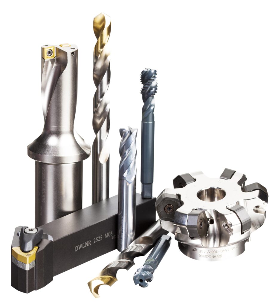
A code like CNMG 120408 looks arbitrary until you know what each character actually stands for — at which point it stops being a mystery and becomes one of the most useful shortcuts in the cutting tools catalogue. Once you can read it, you can specify, cross-reference, and reorder an insert from any brand without needing a part number lookup.
This guide breaks the ISO insert designation code down position by position, based on the ISO 1832 standard that every major manufacturer uses to name their indexable inserts.
Trying to match an insert to your holder? Send our team the code (or a photo of the insert) and we’ll help you find the right match.
What ISO 1832 Actually Standardizes
The ISO designation system for indexable inserts (ISO 1832) is a standardized system for naming an indexable insert, designed so that each important feature and dimension of the insert is captured in a code that becomes the insert’s name. This has real practical value: it gives a unique, supplier-independent name for an insert, states its important features and dimensions clearly, and even encodes details relevant to which holder the insert fits.
There’s one important thing the standard deliberately does not cover: it does not standardize insert quality. Neither the carbide grade nor the cutting geometry (chip-breaker design, edge preparation) is standardized by ISO 1832 — those remain each manufacturer’s own proprietary specification, even when two inserts share an identical ISO code.
The full designation can run to 13 symbols, but only the first 7 are mandatory for standard turning inserts — positions 8 onward exist to describe wiper geometry, and CBN or PCD tipped inserts in more detail.
The 7 Mandatory Positions, at a Glance
The seven-symbol code splits into two groups: the first four symbols form the “Design Group” (shape, clearance angle, tolerance class, and fixing/chip-breaker configuration), and the final three form the “Dimensions Group” (size, thickness, and corner radius). It’s standard practice to put a space between the two groups — for example, CNMG 120408.
Position 1: Shape
The first letter sets the insert’s nose angle and cutting-edge count. A larger nose angle gives a stronger cutting edge and supports higher feed rates, but increases cutting force, vibration, and limits application flexibility. A smaller nose angle gives more flexibility and less vibration, at the cost of a weaker edge.
| Symbol | Shape | Nose Angle | Typical Use |
|---|---|---|---|
| C | 80° Rhombic (diamond) | 80° | Most common general-purpose turning shape — good balance of edge strength and flexibility |
| D | 55° Rhombic | 55° | When the 80° C-shape doesn’t allow enough application flexibility for the geometry |
| V | 35° Rhombic | 35° | Broad flexibility, reduced cutting force — finishing thin walls or long shafts |
| S | Square | 90° | High edge strength, 4 cutting corners; higher cutting forces, less flexibility |
| T | Triangular | 60° | Compact relative to edge length; more limited flexibility, relatively weaker edge |
| W | Trigon | 80° | Same edge as C-shape but 3 cutting edges instead of 2; shorter edge, lower clamping quality |
| R | Round | 360° | Strongest possible edge, highest cutting force — mostly long roughing operations |
Position 2: Clearance Angle
This letter refers to the angle between the insert’s sides and its clamping axis. An insert with zero clearance angle is nicknamed a “negative” insert; any other angle makes it a “positive” insert. Negative inserts are double-sided (double the cutting edges), provide the strongest possible edge, and are the typical first choice for roughing and medium external turning. Positive inserts reduce cutting force and vibration, offer more clearance for internal turning in smaller bores, and are the first choice for finishing operations.
Although the full standard defines several clearance angle letters, only four are commonly seen in practice:
- N — Negative insert (0°), e.g. CNMG
- C — Positive insert (7°), e.g. CCMT — the most common positive-angle choice
- P — Positive insert (11°), e.g. TPMT — used when more clearance is needed, mainly on triangular inserts for internal turning
- B — Positive insert (5°), e.g. WBGT — a positive geometry with a stronger cutting edge, common on small or PCD/CBN-tipped inserts

Position 3: Tolerance Class
The standard defines tolerances for just three parameters: the inscribed circle diameter (the limit on insert size), the cutting edge position (which governs repeatability when indexing a corner or replacing an insert), and insert thickness. Every other property, including the nose radius itself, isn’t covered by the standard and is left to each manufacturer’s own internal specification.
Although the standard lists twelve tolerance classes, only two see regular use in practice: M for pressed inserts, and G for ground inserts, which carry a tighter, defined tolerance (±0.025 mm on both diameter and edge position) than pressed inserts.
Position 4: Fixing and Chip-Breaker Configuration
This letter (somewhat unusually) bundles two unrelated pieces of information together: the mounting/clamping style, and whether a chip breaker is present and on which face. There are three broad mounting categories in the standard: no fixing hole at all (common on ceramic and full CBN inserts, where a hole would be a manufacturing risk), a plain cylindrical hole (used with lever-lock clamping), and a cylindrical hole with a countersink (clamped with a screw that also forces the insert downward — the simplest, most space-efficient, and most common design for small or internal tools).
Common letters include G (cylindrical hole, chip breakers on both faces), M (cylindrical hole, chip breaker on one face only — the most common general-purpose configuration), and T (cylindrical hole with a countersink on one side, chip breaker on one face).
Positions 5–7: Size, Thickness, and Corner Radius
The final three positions are two-digit numbers that describe the insert’s basic dimensions. Under the ISO (metric) convention, in most cases the symbol hints directly at the value:
- Position 5 — Size: represents the length of the cutting edge, approximately in millimetres. Each insert shape has its own specific list of size symbols.
- Position 6 — Thickness: measured from the clamping plane to the highest point of the cutting edge, with the symbol approximating the thickness in millimetres (the first digit is generally a leading zero).
- Position 7 — Corner Radius: the symbol is the corner radius in millimetres, multiplied by 10 — so 08 means a 0.8 mm radius, and 04 means a 0.4 mm radius.
Worked Example: Decoding CNMG 120408
- C — 80° rhombic shape, general-purpose turning
- N — Negative insert, 0° clearance angle, double-sided
- M — Medium (pressed) tolerance class
- G — Cylindrical fixing hole, chip breakers on both faces
- 12 — Roughly 12 mm cutting edge length
- 04 — Roughly 4.76 mm insert thickness
- 08 — 0.8 mm corner radius
Put together: an 80° diamond-shaped, negative (double-sided), medium-tolerance, chip-breaker-equipped insert of roughly 12 mm edge length, 4.76 mm thickness, and a 0.8 mm nose radius — a common general-purpose roughing insert for external turning.
Have an insert code but need it in stock? Send us the code and we’ll confirm availability and compatible holders.
What the ISO Code Doesn’t Tell You
Because ISO 1832 doesn’t standardize carbide grade or cutting geometry, two inserts with an identical code from two different manufacturers can perform very differently in the cut. The code guarantees the insert will physically fit the intended holder and pocket — it says nothing about which carbide grade, coating, or chip-breaker geometry sits behind that shared code. Grade selection and geometry are chosen separately, based on the workpiece material and operation, using each manufacturer’s own grade and geometry recommendations.
Common Mistakes Reading Insert Codes
Assuming the Same Code Means the Same Insert Across Brands
A CNMG 120408 from one manufacturer and another are physically interchangeable, but their carbide grade and chip-breaker geometry are proprietary — assuming identical cutting performance from a matching code is a common and costly mistake.
Confusing the Corner Radius Symbol with Its Value in mm
The radius symbol is the radius in millimetres multiplied by 10 — reading “08” as 8 mm instead of 0.8 mm is an easy, damaging misread.
Ignoring Position 3 (Tolerance Class) When Repeatability Matters
On jobs where indexing to a fresh corner needs to hold a tight, repeatable dimension, the difference between a pressed (M) and ground (G) tolerance insert is directly relevant — not a detail to skip past.
Reading Only the First 4 Symbols and Ignoring Size/Thickness/Radius
The Design Group (first 4 symbols) describes the insert’s outline and clamping, but the Dimensions Group (final 3 symbols) is what actually confirms it will physically fit the intended pocket and produce the intended finish.
Sourcing ISO Indexable Inserts in Dubai
Khokhawala Trading LLC supplies premium carbide tooling systems for CNC machining, metal cutting, milling, turning, and drilling in Dubai and across the UAE.
KTRDG’s carbide tooling range includes products from Sandvik Coromant, Kennametal, Korloy, and Mitsubishi — leading names in indexable insert manufacturing, all designating their inserts under the same ISO 1832 system.



With more than 35 years of industrial tool supply experience, Khokhawala Trading LLC serves manufacturers, CNC shops, fabrication companies, and engineering industries in the UAE.
Ready to shop indexable inserts? Browse our carbide tooling systems range or reach out with your requirement for a fast quote.
A Quick ISO Insert Code Checklist
- Have you confirmed the shape (Position 1) matches your holder’s pocket geometry?
- Is the clearance angle (Position 2) — negative or positive — right for your setup’s rigidity?
- Does the tolerance class (Position 3) matter for this job’s repeatability requirements?
- Does the fixing/chip-breaker configuration (Position 4) match your actual clamping mechanism?
- Have you double-checked the size, thickness, and radius (Positions 5–7) against the physical pocket, not just assumed from a similar code?
- Have you separately confirmed the carbide grade and geometry — since the ISO code alone won’t tell you this?
Conclusion
The ISO 1832 designation system turns a cryptic-looking insert code into a precise physical specification — shape, clearance angle, tolerance class, clamping style, size, thickness, and corner radius, all in seven characters. What it deliberately leaves out is just as important to remember: carbide grade and cutting geometry aren’t standardized, so a matching code across two brands guarantees fit, not performance.
For businesses sourcing indexable inserts in Dubai, Khokhawala Trading LLC supplies Sandvik Coromant, Kennametal, Korloy, and Mitsubishi carbide tooling for CNC machining, milling, turning, and drilling applications.
Need Help Matching an Insert Code?
Send us the code, or a photo of the insert, and Khokhawala Trading LLC will help you find the right match.
ISO Insert Designation Codes, Answered
ISO 1832 is a standardized naming system for indexable inserts that captures each important feature and dimension in a code. It gives a unique, supplier-independent name and clearly states key features and dimensions, but it does not standardize carbide grade or cutting geometry.
The full designation can contain up to 13 symbols, but only the first 7 are mandatory for standard turning inserts. Positions 8 and beyond describe wiper geometry and CBN or PCD tipped inserts in more detail.
N in position 2 indicates a 0° clearance angle, making it a “negative” insert. Negative inserts are double-sided, offering double the cutting edges, and provide the strongest possible cutting edge, making them a common choice for roughing and medium external turning.
M is for pressed inserts, and G is for ground inserts, which carry a tighter, defined tolerance of ±0.025 mm on both diameter and cutting-edge position. These are the two tolerance classes used in practice out of twelve defined in the full standard.
The corner radius symbol (position 7) is the radius in millimetres multiplied by 10. So “08” means a 0.8 mm radius, and “04” means a 0.4 mm radius — not 8 mm or 4 mm.
Not necessarily. ISO 1832 doesn’t standardize carbide grade or cutting geometry, so two inserts sharing an identical code from different manufacturers will fit the same holder but can still perform very differently, depending on each manufacturer’s proprietary grade and geometry.
Negative inserts (0° clearance) are double-sided and provide the strongest cutting edge — suited to roughing and rigid setups. Positive inserts (any other clearance angle) reduce cutting force and vibration and allow machining inside smaller bores, making them the typical choice for finishing operations.
The shape letter sets the nose angle, which directly affects edge strength versus application flexibility. A larger nose angle (like the 80° C-shape) gives a stronger edge and higher feed rates but more cutting force and vibration; a smaller nose angle (like 35° V-shape) gives more flexibility with a weaker edge.
Some code positions relate directly to the insert holder the insert can be mounted in, particularly the shape, fixing/clamping configuration, and size — but the holder itself is specified separately, using its own designation system referencing the insert it’s built for.
Khokhawala Trading LLC supplies carbide tooling systems in Dubai and across the UAE, including Sandvik Coromant, Kennametal, Korloy, and Mitsubishi indexable inserts.