
Spindle Speed and Feed Rate: How to Calculate the Right Settings for CNC Machining
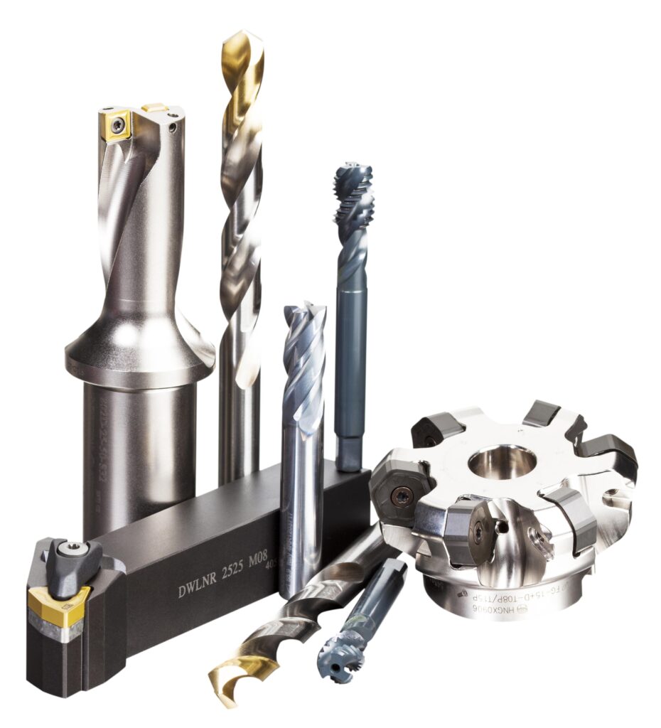
Two numbers go into almost every CNC program: how fast the spindle turns, and how fast the tool moves through the material. Get them wrong and you get burned edges, broken tools, chatter, or a part that takes twice as long as it should.
The good news is that both numbers come from short formulas. This guide shows how to work them out, what you need to know before you start, and why the calculated figure is a starting point you then tune on the machine.
Not sure what cutting data suits your tool and material? Tell our team the tool and the workpiece, and we’ll help you find the manufacturer’s recommended starting values.
Cutting Speed, Spindle Speed, and Feed Rate: Three Different Numbers
“Speeds and feeds” refers to two separate parameters: cutting speed and feed rate. They’re considered a pair because of their combined effect on the cut, but each is its own thing.
- Cutting speed (also called surface speed) is the relative velocity between the cutting tool and the workpiece surface, expressed in surface feet per minute (SFM) or metres per minute (m/min).
- Spindle speed is the rotational frequency of the spindle, measured in revolutions per minute (RPM). It is worked out from the cutting speed you want and the diameter involved.
- Feed rate is the velocity at which the cutter is advanced along the workpiece. Its direction is perpendicular to the cutting speed.
Units depend on the operation. In turning and boring, where the workpiece rotates, feed is almost always distance per spindle revolution (mm/rev or in/rev). In milling, where the workpiece doesn’t rotate, feed is typically distance per time (mm/min or in/min).
Step 1: Find the Cutting Speed
There is an optimum cutting speed for each material and set of machining conditions. Three things drive it: the material being machined, the material the cutter is made from (high-carbon steel, HSS, carbide, ceramic, or diamond), and the economical life you want from the cutter.
Cutting speeds come from the material or tool supplier, in reference books and charts, and the tool manufacturer’s tables are the best starting point for a specific tool. They always need adjusting to the actual conditions. As a reference, Wikipedia gives these cutting speeds for a plain HSS cutter, under one specific set of conditions (1 hour tool life, dry cutting with no coolant, medium feeds):
| Material | m/min | SFM |
|---|---|---|
| Aluminium | 122–305 | 400–1000 |
| Brass | 90–210 | 300–700 |
| Free-cutting steels | 35–69 | 115–225 |
These are for plain HSS. Carbide runs considerably faster, and values change with coolant and tool grade, so treat the table as a feel for how much materials differ rather than as settings to program.
Step 2: Calculate the Spindle Speed (RPM)
Once you have a cutting speed, work backward to RPM using the diameter of the cutter (milling, drilling) or of the workpiece (turning). In drilling and milling the outside diameter of the tool is the widely agreed reference. In turning, the largest diameter is the usual focus, because that’s where tangential speed and heat are highest.
Metric:
Imperial:
Machinists often use a simplified version with π rounded, since an exact RPM isn’t always needed and a close approximation works. Wikipedia’s own examples: a cutting speed of 100 ft/min on a 10-inch diameter works out to about 38 RPM, and 30 m/min on a 10 mm diameter works out to about 955 RPM.
Step 3: Calculate the Feed Rate
For milling, drilling, and other multi-tooth cutters, feed rate depends on how many teeth the cutter has and how much material each tooth should cut. That per-tooth figure is the chip load (feed per tooth).
The result is in mm/min or in/min, depending on whether chip load is in mm or inches per tooth. This formula is for milling-type cutters. It is not used for turning on a lathe, where feed is given per revolution.
The more cutting edges a tool has, the higher the feed rate it can take, because each edge still has to remove enough material to cut rather than rub.
Worked Example (Illustrative Inputs)
Take a 10 mm, 2-flute end mill. The cutting speed is 30 m/min, and the chip load is 0.05 mm per tooth. Both inputs here are only for illustration. For a real job, take them from the tool manufacturer’s data for your material.
- RPM = (30 × 1000) ÷ (π × 10) ≈ 955 RPM
- Feed rate = 955 × 2 × 0.05 ≈ 95.5 mm/min
Note how the pieces connect: to raise the feed rate while holding the same chip load, you either raise the RPM or use a cutter with more flutes.

Need cutters with published cutting data? Send us the material and operation and we’ll match you with a tool from the brands we carry.
What the Calculated Numbers Assume
Published cutting speeds assume optimum conditions. Move away from them and the numbers need adjusting, usually by dropping the RPM to the nearest suitable speed. The assumptions are:
- A full, constant flow of cutting fluid for cooling and chip flushing.
- A rigid machine and tooling setup, with no vibration or chatter.
- A continuous cut rather than an interrupted one.
- Material in good condition, without mill scale or hard spots.
- A metal removal rate that suits the cut. Light finishing cuts can run faster.
In practice, lack of rigidity is usually the limiting constraint, not spindle power. That’s why a setup with a long tool overhang can’t run the speeds the machine and tool are nominally capable of.
What Changes the Feed Rate You Can Use
Feed rate depends on more than the formula:
- The type of tool, including its size, and whether it is HSS or carbide.
- The surface finish you need.
- The power available at the spindle, so the cutter doesn’t stall.
- The rigidity of the machine and tooling setup.
- The strength of the workpiece. High feed rates can collapse thin-wall tubing.
- The material and its chip flow. The ideal chip is small and breaks free early, carrying heat away from the tool and the work.
- The width of cut.
Chip Thinning
Any time the width of cut is less than half the cutter diameter, a geometric effect called chip thinning reduces the actual chip load. Feed rates need to be increased to offset it, both for productivity and to avoid rubbing, which shortens tool life.
Constant Surface Speed on a Lathe
Facing, forming, parting off, and recessing on a lathe machine a constantly changing diameter. Ideally the spindle speed rises as the cut moves toward the centre so surface speed stays constant. CNC lathes make this practical through automated constant surface speed (CSS), using variable-speed spindle drives.
Why Stainless Steel Needs Extra Care
Some materials forgive a wide range of spindle speeds. Machinable wax is one. Others, such as stainless steel, need much more careful control, because cutting speed is critical to avoid overheating both the cutter and the workpiece.
Stainless also hardens easily under cold working. Insufficient feed rate or an incorrect spindle speed lets the workpiece harden quickly and resist the tool. Generous cutting fluid helps, but correct speed selection is the critical factor.
What Happens When the Settings Are Off
Excessive spindle speed causes premature tool wear, breakage, and chatter, all of which can create dangerous conditions. The correct spindle speed for the material and tool greatly improves tool life and surface finish.
The ratio of spindle speed to feed rate controls how aggressive the cut is and the nature of the swarf formed. Too little feed makes the edge rub instead of cut, and too much overloads it.
Treat the Calculation as a Starting Point
Speed-and-feed selection can be modelled with charts and formulas, but like weather forecasting, the models can’t fully predict a specific case. Machinists can predict the approximate values that will work best, but cannot know the optimal values until they run the job.
In CNC machining, the programmer sets speeds and feeds as well tuned as calculations and guidelines allow. The operator then fine-tunes while the machine runs, based on sights, sounds, smells, temperatures, tolerance holding, and how long the tool tip lasts. Under proper management, the revised values are recorded so the next run of the program doesn’t repeat the work.
Common Mistakes
Using One Cutting Speed for Every Tool Material
Cutting speed depends on both the workpiece and the cutter material. A figure for plain HSS is not a figure for carbide.
Mixing Up Feed per Tooth and Feed Rate
Chip load is per tooth. Feed rate is chip load multiplied by the number of teeth and the RPM. Entering a per-tooth value where a per-minute value is expected is an easy and costly slip.
Using the Milling Formula on a Lathe
The RPM × teeth × chip load formula is for milling-type cutters. On a lathe, feed is distance per revolution.
Ignoring Chip Thinning on Light Radial Cuts
When width of cut drops below half the diameter, the actual chip is thinner than the programmed chip load, and rubbing shortens tool life unless feed is raised.
Pushing the Calculated Speed on a Setup That Isn’t Rigid
The formula doesn’t know about overhang or workholding. If the setup vibrates, reduce the RPM and check rigidity before blaming the numbers.
Sourcing Cutting Tools With Published Cutting Data in Dubai
Khokhawala Trading LLC supplies premium carbide tooling systems for CNC machining, metal cutting, milling, turning, and drilling in Dubai and across the UAE.
KTRDG’s carbide tooling range includes products from Sandvik Coromant, Kennametal, Korloy, and Mitsubishi. Each publishes its own recommended cutting data for its tools and grades, which is the right source for the cutting speed and chip load inputs above.




With more than 35 years of industrial tool supply experience, Khokhawala Trading LLC serves manufacturers, CNC shops, fabrication companies, and engineering industries in the UAE.
Ready to shop carbide tooling? Browse the carbide tooling systems range or reach out with your requirement for a fast quote.
A Quick Speeds and Feeds Checklist
- Do you have the cutting speed for this workpiece material and this cutter material, from the tool manufacturer?
- Have you used the right diameter (cutter OD for milling and drilling, largest workpiece diameter for turning)?
- Is the feed formula matched to the operation: feed per minute for milling, feed per revolution for turning?
- Is the chip load per tooth from the tool manufacturer rather than a guess?
- Is the radial width of cut under half the diameter, so chip thinning needs compensating?
- Is coolant flowing, and is the setup rigid enough for the calculated speed?
- On a lathe facing or parting job, is constant surface speed switched on?
- Are you recording the tuned values so the next run starts from them?
Conclusion
Spindle speed comes from the cutting speed and the diameter. Feed rate comes from that RPM, the number of teeth, and the chip load. Both formulas are short, but the inputs aren’t universal: cutting speed depends on the workpiece and the cutter material, and chip load depends on the tool and the cut.
Calculate, then run the job and tune by sound, finish, and tool life, then keep the values that worked. For businesses sourcing carbide tooling in Dubai, Khokhawala Trading LLC supplies Sandvik Coromant, Kennametal, Korloy, and Mitsubishi tooling for CNC machining, milling, turning, and drilling.
Need Help Dialling In a Job?
Send us your material, tool, and operation, and Khokhawala Trading LLC will help you find the right tooling and starting data.
Spindle Speed and Feed Rate, Answered
Cutting speed is the relative velocity between the cutting tool and the workpiece surface, in SFM or m/min. Spindle speed is the rotational frequency of the spindle in RPM, calculated from the cutting speed and the tool or workpiece diameter.
In metric units, RPM equals cutting speed in m/min times 1000, divided by π times the diameter in mm. In imperial units, RPM equals cutting speed in SFM times 12, divided by π times the diameter in inches.
Feed rate equals RPM times the number of teeth on the cutter times the chip load (feed per tooth). The result is in mm/min or in/min depending on the units of the chip load.
Chip load, or feed per tooth, is the size of the chip each tooth of the cutter takes. Each cutting edge must remove enough material to cut rather than rub, which is why a cutter with more teeth can be fed faster.
Yes. In turning and boring, feed is almost always distance per spindle revolution (mm/rev or in/rev). In milling it is typically distance per time (mm/min or in/min), and the milling feed formula is not used for lathe turning.
Excessive spindle speed causes premature tool wear, breakage, and tool chatter, all of which can lead to potentially dangerous conditions. The correct speed for the material and tool greatly enhances tool life and surface finish.
When the width of cut is less than half the cutter diameter, a geometric effect reduces the actual chip load. Feed rates need to be increased to offset it, both for productivity and to avoid rubbing that reduces tool life.
Stainless steel requires careful control of cutting speed to avoid overheating the cutter and workpiece, and it work hardens easily. Too little feed or the wrong spindle speed lets the workpiece harden and resist the tool.
No. Charts and formulas predict approximate values, but the optimal ones aren’t known until the job runs. Operators fine-tune based on sights, sounds, smells, temperatures, tolerance holding, and tool life, and the revised values are recorded for next time.
Khokhawala Trading LLC supplies carbide tooling systems in Dubai and across the UAE, including Sandvik Coromant, Kennametal, Korloy, and Mitsubishi products.